详细说明
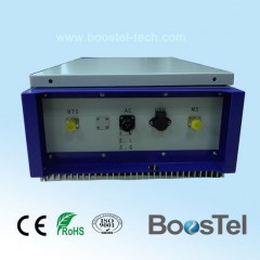
Product Name: PCS 1900MHz Channel Selective Booster Signal Amplifier Model NO.: BT-PA43H4 Condition: New Certification: ISO, CE Lightning Protection: Lightning Arrester Standard: Standard Transmission Medium: Wireless Type: Wireless Repeater Trademark: BOOSTEL Transport Package: Wooden Case Specification: 560*450*270mm Origin: China Product Description Specifications of PCS1900 Channel Selective RF RepeaterModel: BT-PA43H4The RF Repeater (RFR) is designed to provide a more cost-effective solution than adding a new base Transceiver Station (BTS) to improve signal coverage and communication quality in DCS1800 system. And its easy installation and maintenance can help carrier get fast return.The repeater is working as a relay between the BTS and mobiles. It receives the low-power signal from BTS via the Donor Antenna, linearly amplifies the signal and then retransmits it via the Coverage Antenna to the weak/blind coverage area. And the mobile signal is also amplified and retransmitted to the BTS via the opposite direction.Features Aluminum-alloy casing with IP65 protection has high resistance to dust, water and corrodingNo interference to BTS by adopting linear amplifier with high gain and low noiseAdopting filter with highly selectivity and low insertion loss eliminates interference between uplink and downlinkUSB port provides a link to a notebook for local supervision or to the built-in wireless modem to communicate with the NMS (Network Management System) that can remotely supervise repeater's working status and download operational parameters to the repeaterApplications To expand signal coverage or fill signal blind area where signal is weak or unavailable.Outdoor:Airports, tourism regions, golf courses, tunnels, factories, mining districts, villages, …Indoor:Hotels, exhibition centers, basements, shopping malls, offices, parking lots, … Application Diagram Technical SpecificationsItemSpecificationsWorking Frequency (Customized)Uplink1865~1895 MHz Downlink1945~ 1975 MHz No. of Channels4Maximum Input Power (Non-Destructive)10dBmOutput Power(Customized)43dBmGain≥ 90dBGain Adjustment Range1~31 dB @ step of 1 dBVoltage Standing Wave Ratio< 1.5Noise Figure≤ 5dBIn-band Ripple≤6dBSpurious EmissionWithin working band≤ -15dBm/30kHzOut of working band(f > 2.5MHz)9kHz~1GHz: ≤ -36dBm/30kHz1GHz~12.75GHz: ≤ -30dBm/30kHzThird-order Inter-modulation ≤ -45dBc / 30kHz (measured under rated output power)System Delay≤1.5μSecI/O Impedance50ΩRF ConnectorN-Type (Female) / Changeable / bottom of casingTemperature RangeOperation: -25°C ~ + 55°C / Storage: -30°C ~ +60°CRelative Humidity Range≤ 95% (non condensing)Power Supply (customized)DC +24V / AC 220V±15% or AC 110V±15%, 50HzPower consumption≤150WBackup Power Supply (optional)4 hoursCasing LevelIP65Dimensions600*400*230mmWeight35kgControl ConnectorUSB port for local / remoteNMS Monitoring Function(Optional)Real-time alarm for door status, temperature, power supply, LNA, VSWR, self-oscillation, etc;Remote control such as turn on/off, increasing/decreasing output power etc;Real-time status for output/input power, UL/DL gain, all status of repeater etc.Installation & Commissioning1.1 Installation1.1.1 Steps for mounting on the PoleAt Donor site, install the FSR Donor Unit, Donor Antenna, link Antenna, and RF cable as per specified plan and site layout. FSR Donor Unit can be pole-mounted using the brackets as shown below.Place M8 screws through the holes of H type brackets as shown in figure 1Fix combiner onto the H type brackets with M6 screwsFix H type brackets with combiner installed onto the pole with U type brackets and M8 screwsFigure 1 Repeater Mounting BracketOrient the link Antenna of Donor Site to the direction of the Remote Site.Use Site Master to measure the VSWR of the RF cable from the link Antenna. The value should be less than 1.5; Otherwise, check the connectors and the installation of the cable.Start Commissioning the Donor Unit .Proceed to the Remote Site.At Remote site, install the FSR Remote Unit, link Antenna, Coverage Antenna, and RF cables. Remote Unit can be wall mounted or pole mounted depending on the approved plan.Orient the Remote link Antenna to the direction of the Donor Site.Using Spectrum Analyzer, check the link RSL; adjust the link Antennas of both Donor and Remote until the required RSL is achieved. link RSL can be computed using conventional path calculation method.Then, measure the VSWR of the RF cables connecting with the link Antenna of Remote Unit. The value should be less than 1.5, otherwise, check the connectors and the installation of the cable.Start Commissioning the Remote Unit .1.1.2 Steps for mounting on the wallAt Donor site, install the FSR Donor Unit, Donor Antenna, link Antenna, and RF cable as per specified plan and site layout. FSR Donor Unit can be wall-mounted using the brackets as shown below.Make four marks on the wall according to the dimension shown as figure 2Drill four holes at position markedFix two pcs H type brackets on the wall with M8 expansion screwsFix combiner onto the brackets with M6 screwsFigure 2 Repeater Mounting Bracket 6. The following steps are the same with step 4 to 12 for mounting on the Pole.1.2 CommissioningConnect the RF cable from Donor Antenna to the spectrum analyzer and check if the Donor Antenna is receiving the correct frequency; and then measure the signal level of the said frequency (RSL). Adjust the antenna to make the readings approach the recorded value on the survey report. Record all readings.Inside the repeater, disconnect the uplink duplexer to the ICS module so as to cut any signal coming from air going to the uplink duplexer and thus protecting the amplifier from damaging. Connect a 30 dB attenuator to the output of the repeater; this attenuator will serve as a load for the repeater. The purpose of this attenuator is to protect the equipments from damaging.Turn ON the repeater. Observe the LED display on the NMS board. Check for any alarm. Under normal condition, the POWER LED should be always green and the RUN LED should be blinking, the ALARM LED should be not bright with red color.Figure3Interface of NMS BoardConnect your laptop to the repeater via the data cable.