详细说明
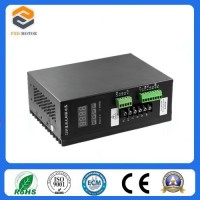
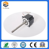
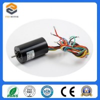
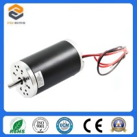
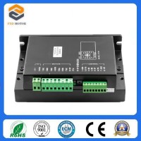
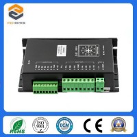
Product Name: Made in China Electric DC Brushless Motor Driver with Ce Certification (BLMD-08) Model NO.: BLMD-08 Material: Aluminum Alloy Customized: Customized Condition: New Certification: RoHS, CCC, ISO: 9001, CE Function: Automatic Control Signal: Continuous Mathematical Model: Non-Linear Structure: Combination Task: Control Power Input Type: AC Vlotage 180V-250V Output Current: 9.9 a Dimensions: 180 * 80 * 140 Price: Negotiable and Competitive Price Min Order: 1 PC (Sample) Port: Shanghai Trademark: fxd motors Transport Package: Form Box and Carton Specification: CE, ROHS Origin: Changzhou City Jiangsu Province China HS Code: 8501310000 Product Description Preface220VAC BL drives is a powerful driver designed by Changzhou Fuxianda Electromechanical Co., Ltd which is assorted with the advanced motion control industrial. The drives adopt the latest DSP specialized for motor as the core technical matched with high speed digital logic chips and high quality power module. It gets the advantage on highly integration, small volume, well protection, high reliability etc. This drives can provide: panel speed adjust command, external simulative voltage, external potentiometer, pulse width speed adjust etc.1. System Characteristic:1Input VoltageAC180-250VAC, 50/60Hz2Continuous Output current4.9A, suit for less than 1000W brushless motors3Max. Output current9.9A4Working temp0~+45°C5Storage temp-20~+85°C6Working & storage humidity<85% no frosting7Structurewall-mountable box type8DimensionL180 x W80 x H140mm2. Basic Characteristic1CoolingRadiator2Control terminalsIsolation3ProtectionOver load, over heat, over speed, over voltage, lost voltage will cause the power abnormity4Panel6 digit LED display, 4 digit keypad operation3. Installation attention* Do not measuring or touch any components without housing while operating.* Should check soleplate or change fuse 1minter later after power off.* Operating without housing is forbidden.* Make sure to connect the ground terminal, otherwise the brushless motor will working unsteadily* Sudden damage while drives working, our company only affords the service and replace in guarantee. Personal injury and motor damage caused by the accident will invalidate the guarantee.4. Power Terminal and Motor TerminalNo.Terminal NameSignal Function1L1(L)(R)Power input of main circuitMain circuit power input terminal AC220V 50Hz, Connect L1 and L2 while using single phase voltage 220V2L2(N)(S)3L3(T)4PHigh voltage DC bus line terminalDC bus line terminal in driver, rated power 315V5B1internal brake resistance When using internal brake resistance, short circuit B1 and B2, when the power is not enough, need to use external brake resistance, break B1 and B2, connect external brake resistance with P and B2 6B2external brake resistance7U(MA)OutputThe motor terminals must be connected with U,V,W one-to- one. Attention: do not reverse the motor by exchange 3 phase terminals, it is completely different with asynchronous motor8V(MB)9W(MC)PEProtection The release way is supplied for protection motor and drive when current leakage5. Parameters setup5.1 Parameters P1 This series characteristics are used to set up some functions by clients self, they can be self-adjust according to clients' different demand. They are operation functions, have no relation with fundamental characteristics of driverFunction NameNo.Value RangeDefault Value Function SpecificationDisplay optionalP1.00~900. display real speed1. display DC voltage of main circuit2. display external analog input3. display motor current4. display internal program speed5. U phase current6. V phase current7. W phase current8. duty ratio9 .preserveInternal running speedP1.10~99992000When choose internal speed, the data will decide motor's speed(view P1.2)Choose signal sourcing of speed P1.20~210:internal instruct speed(tP1[0] is internal speed, when motor running, MUP to up speed ,MDOWN to reduce speed)1: external terminal analog input, using SV signal of 7 pin of CN2 as motor's speed.2:communication order controlDirection settingP1.30~100: CW1: CCWChoose signal sourcing of start-stopP1.40~210:button by hand control(ENT is start-stop, SET is reverse motor, +/- is for up and reduce speed)1:external terminal control: using 4pin signal of CN2 to start and stop motor2: communication order control pole pairs of motorP1.50~992attention: pole pairs=pole/2Driver location P1.60~2550The driver location when Using communication to control motorSpeed scale factorP1.70~999991520Scale factor using for PID speed control (KP)Speed integrating factor P1.80~99999320Integrating factor using for PID speed control(KI)Accelerated speed P1.91~600006000The parameters is directly proportional to accelerated speed, the real accelerated speed is based on loading of motor Decelerated speed P1.101~600006000Rated speed settingP1.110~999993000Speed corresponding maximum analog input (unit: RPM)Analog input dead bandP1.120~3300100The function is used to set input voltage when motor speed is 0 (unit: mV)Manual operation to adjust speed equivalentP1.131~9991Use bottom to change the speed equivalent under internal speed type ( speed changed per press)Recover default parameters P1.140~10Set up 1 then quit setting, connecting the power again, all parameters will recover to default value.5.2 Control panel operationAs picture on left, there are 4 keys on the panel,"SET": press this key can enter or quite P1 setup menu""and "": "+"and "-", to choose the function and adjust the parameters. Otherwise, "+"is the hotkey to enter trial operation function."ENT": "/confirm/iation" and "operation", when setting parameters, press this button to enter adjustment interface and jump. Under trial operation type, press ENT to start or stop motor.Display instruction: total 6 digital tube shows "888888", the light most is first and the lowestAttention: The adjustment is forbidden if the adjusted value is larger than the maximum allowed, the bottom will be no response.5.3 How to set parametersExample:Demand: set internal speed (P1.1) to 1000rpm/minOperation step as below:1. After connecting with power, display "H 0", the driver is standby, press "SET", will display"P0. 0"2. Press "SET", display "P1 0", the driver is entering P1 setting state3.Press "", until display "P1. 4"4. Press "ENT", display "2000", and the first of light most is flashing5. Press "ENT", until the flashing is moving to the fourth position6. Press "", change into "1000"7. Press "SET", display "P1. 4", the parameters had been set up and save automatic8. Press "SET" again, display "P2 0"9. Press "SET" again, back to standby state, display "H 0", now; the new parameters adjustment had finished and takes effectAttention: 1. after adjustment, the driver need to connect with power again, then the new parameters will take effect 2. The parameters with "" in the list can not been adjust when motor working3. The adjustment is forbidden if the adjusted value is larger than the maximum allowed, the bottom be will no response 6. Wiring Diagram7. Functions7.1. Speed adjustment methodThis driver provide below three adjust methods for the user to choose:Analog voltage adjustment speed: the terminals of external potentiometer connect to the +5v terminal in signal control and COM, connect the regulator terminal to SV, not only make it possible to adjust speed by external potentiometer (10K~100K), but also can achieve speed adjust through other control unit (Such as PLC, Microcontroller, etc) input analog voltage to SV. The acceptance of SV is DC 0V~+5V, and the corresponding motor rotate speed is 0 to rated speed.You also can use external digital signal to adjust speed: apply PWM with 5V amplitude and 1 KHz~2 KHz Frequency between SV and GND to adjust the speed. The motor rotate speed will adjust by the duty radio liner adjustment.The third method to adjust speed is using communication order controlling 7.2. Motor operate/stop control (EN)You can control the brushless motor to run or stop by controlling the terminal "EN" and "COM" connecting.The motor will run when we connect the terminal "EN" to "COM"; when shut down, the motor will stop naturally. And the starting time will decided by the initial setup in panel, the motor running will be affected by load added7.3. Motor rotation direction control (F/R)You can control the motor rotation direction by controlling the terminal "F/R" and "COM" connecting. When connect terminal "F/R" to terminal "COM", the motor will run at CCW (view from motor output side), and when shut down, the motor will run at another direction.Attention: If you need to change the motor rotation direction, please stop the motor at first, otherwise the controller shall be caused to damage.7.4. Break the motor to stop (BK)You can break the motor to stop if need. Motor can be running when the terminal "BK" not connects to "COM", but if you connect these two terminal together, motor will stop quickly. If the overload alarm frequently, you need to add brake resistance for driver, the resistance value is not less than 100Ω, and power is not less than 100W. Attention: when install the brake resistance, the driver must be under without power and indicating light state. The brake resistance accessories is for charge7.5. Speed signal output (PG)The speed pulse output is 0C, output 30V/10mA max. You can connect with a resistance (3K ohm ~10K ohm) between "PG" and the input power to get the speed pulse signal. The relationship of output frequency F (Hz) and speed N(rpm)is: F=N * P / 60 , P is the pole pairs of motor, Output Pulse per revolution.7.6. Alarm output (ALM)The alarm output port is 0C, output 30V/10mA max. You can connect with a resistance (3K ohm ~ 10 K ohms) between ALARM output and the input power to get the alarm signal. When alarm, this port and the GND connecting (Low voltage), and the controller will stop working and keep in alarm status.8Working methods The driver has three working methods by setting panel. The first is panel manual operation, press R/S to start or stop the motor, press + - to up or reduce the speed, press" ←"ENTER to confirm the speed. The second is by external terminals, the motor is working with settle, digital tube display running speed. The third method is communication type.9 Protection typeWhen the motor is running abnormally, the digital tube will display:1OLmotor locked2OCover current3HEhall signal failure4LVunder voltage input5HUover voltage input6EEIPM failure protection7OTmotor too hot 10 System usingFirstly, connect motor and driver lines (wounding lines, hall signal lines and power line) in strictly observe related norms and specification. It can't to reverse the motor by change lines connection, it is completely different with asynchronous motor. The motor and driver can not work normally even damaged if lines connected wrongYou can start the trial operation after connecting motor power line, hall line and driver power lines. At first, set the control panel or terminal control, secondly set the pole pairs of brushless DC motor (wrong pole pairs will display inaccurate speed and offer wrong inner parameter ), then press the start button, enlarge the potentiometer slightly , the motor will run, if the motor do not work, or shake, or alarm, maybe the lines connection is not correct, or load is too large, please check again, until the motor running normally. Parts of our Products