详细说明
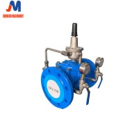
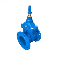
Product Name: Hydraulic Control Valve/Pressure Reducing Valve/Pressure Relief and Pressure Sustaining Valve/Float Control Valve Model NO.: from DN40 to DN400 Material: Cast Iron Structure: Diaphragm Valve Seat: Single-Seat Connection: Flange Temperature: Ordinary Temperature Certification: CCC, RoHS, ISO, CE Standard: DIN/BS/Cj/T219/GB5135.17 Media: Water Certificate: Material Certificate 3.1,Ce Certificate Color: up to Client Warranty: 24 Months Quality Control: 100% Inspection and ISO9001 Quality Control System Trademark: JUDBERD Transport Package: Sea Worthy Plywood Box Specification: DN40 to DN1200 Origin: China HS Code: 8481804090 Product Description Product DescriptionPressure reducing valveThis valve is designed and manufactured by our company according to the advanced product of the same type in the United States, France and China.The valve body adopts the streamlined design with less internal head loss and large flow. The transmission mode adopts the hydraulic operation, and thepipeline pressure is used to automatically control the up and down movement of valve disc, control the valve opening, and adjust the downstream pressure, so as to maintain the downstream pressure above the pilot valve spring set value. When the downstream pressure exceeds the set value, the valve will shutdown automatically, and guarantee the constant outlet pressure.The product is the ideal product used for domestic water, fire system and water supply system.2. Structural The valve consists of the main valve, pilot valve, needle valve, ball valve, micro filter and pressure gauge etc. The pilot valve, needle valve, ball valve andpressure gauge are connected to the main valve with pipe, so it is collectively called as the pipe control system, as shown in the below picture.1. Needle valve; 2. Pressure reducing valve; 3. Ball valve3. Main specificationOur pressure reducing valve drawing is as below4. Main dimensionMain DimensionDN40506580100125150200250300350400450500600L2052052502503204154155006056907877878649141067H1112115128147174214224287336402480510598669754Control FlowMin0.50.5511.22.98.59.215284578117210336490Max21374650951702303608001090140218702316282940305. Working principle and purpose The pressure P1 enters the control room of main valve through pipe and needle valve 23 (see the chart), and establishes the downward pressure P3. Theoutlet pressure P2 can act on the diaphragm of pilot valve 22 through the pipe and conflict with the adjustment spring of pilot valve. When the downstreampressure exceeds the pilot valve spring set value, the pilot valve will be closed, the water discharge in the control chamber is 0, and the variable pressure F3reaches the maximum value, and the main valve pressure seat valve is closed tightly. When the downstream pressure is less than the pilot valve spring setvalue, the pilot valve will open, and the water discharge in the control chamber will pass downstream through the pilot valve 22 and ball valve 19. The needlevalve opening is small (1/4-1/2), and the inlet duct is smaller than the outlet duct in the diameter, so the discharge speed is greater than the inlet pressure fillingspeed, thus the pressure F3 in the control room is reduced, and the inlet pressure P1 acts on main valve disc 23 and raises it, so as to open the decompression valve.In the steady regulation state, the discharge flow is equal to the filling flow, the main valve opening is unchanged, and the downstream pressure is stable.6. Installation and adjustment1. The optimal installation of main valve is horizontal installation with pump cover up. Other installation methods can also realize the use function, and it isnecessary to thoroughly remove the sundries in the pipe before installation. Pay attention to the flow direction arrow on the main valve body, and follow thecorrect direction. Ensure that no pipe stress is on the valve body and internal parts after installation.2. Before the installation of main valve, a gate valve and a filter should be installed, and a gate valve should also be installed behind the main valve for repair.3. Regularly clean the micro filter 24 on the main valve.4. Thoroughly flush the pipe before filling water.5. Install the bypass-valve for important water pipe6. Pressure regulation method1) Close the upstream isolation valve, open the downstream isolation valve for decompression, and lower the downstream pressure below 0.1MPa, and closethe downstream isolation valve;2) Rotate the pilot valve adjusting screw to the top position;3) Open the upstream isolation valve slowly;4) Tighten the pilot valve adjusting screw down, and the outlet pressure will gradually rise, and lock the adjusting screw until reaching the set value; 5) Under the excessive pressure regulation, adjust from the first step; that is, adjust from low to high pressure.Installation drawing of 200X pressure reducing valve1, 4, 5: resilient seat gate valve; 2. strainer; 3. 200X pressure reducing valve;For more details,please contact us .Our Process for Pressure reducing valve production is as belowWe Produce our product strictly according to ISO9001 quality control system,and we have WRAS ,DVGW, ,ISO14001 certificate for powder,and WRAS certificate for EPDM gasket.Photos as below are for your referenceour Package is sea worthy polywood box or pallet,photos are as belowWe control our quality according to ISO9001 ,photos as below is for your referencewelcome your enquiry ,we will do our best to support.