详细说明
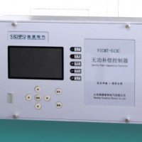
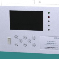
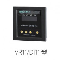
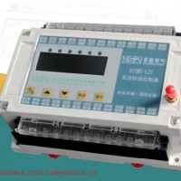
Product Name: High-Voltage Reactive Powercompensation Controller Model NO.: VQC controller Material: Aluminum Alloy Customized: Customized Condition: Used Certification: RoHS, CCC, ISO: 9001, CE Function: Automatic Control, Protection, Monitoring, Measurement Signal: Continuous Mathematical Model: Linear Structure: Combination Task: Program Trademark: Haiyuan Transport Package: Carton Specification: electronic component Origin: China HS Code: 8537109021 Product Description This "High-Voltage Reactive Power Compensation Controller"is a high-voltage capacitor reactive automatic control device consisting of high-voltage capacitor automatic control and PC protection unit and is called as high-voltage reactive power compensation controller. This device provides capacitor protection, measurement, control and remote network communication function and features excellent price/performance ratio, simple structure, feasibility, powerful function and safe and reliable operation. It can be installed in the central screen or in the distributed switch cabinet (or capacitor bank cabinet), is used for automatic control of reactive power compensation of the power capacitor in 220kV and under substations and 6~35kVpower supply and distribution system, integrates detection, measurementand display, control and analysis, protection and alarm, recording and inquiry. This controller is adapted to single and dual busbar section. Each section can control four banks and maximum 8 capacitor banks. ReferencesDL/T 672-1999 "Technical condition for ordering substation voltage reactive power adjustment control device"DL/T 478-2001 "Generic technical condition for static relay protection and safe automaticdevice"GB/T 50062-2008 "Design specification for power device relay protection and automaticdevice"GB/T 14285-2006"Technical regulation for relay protection and safe automaticdevice"Function ListAutomatic control function this controller can automatically identity and adapt the systemoperation mode and automatically switch the capacitor bank, E.g. parallel operation, separated operation, one section drives whole station. The controller can separately control the capacitor bank and can performjoint control with the protection unit. For joint operation, the protection unit feeds back the alarm signals. Two control strategies The control strategy includes the power factor switching mode and voltage reactive power switching mode. Switching condition of reactive power factor: When the power factor is less than the power factor switch-on threshold and the switch-on capacitorwill not inversely feed, the capacitorswitches on. When the power factor is higher than the power factor switch-off threshold, the capacitor is released. Release the capacitor in case of reactive power inverse feeding. Voltage reactive power switching mode The voltage is preferred in this mode. It is determined by the reactive power value, described as follows: When the current systemvoltage is lower than the voltage switch-on threshold, the capacitor switches on and another capacitor bank will switch on after a while (switch-on delay) till all capacitors switch on. When the current systemvoltage is higher than the voltage switch-off threshold, the capacitor switches off and another capacitor bank will switch off after a while (switch-on delay) till all capacitors switch off.When the current system voltage is betweenswitch-off threshold and switch-on threshold plus ΔUand the reactive power is lower than floor limit of the reactive power, the capacitor switches off. When the current system voltage is betweenswitch-on threshold and switch-on threshold plus ΔUand the reactive power is lower than floor limit of the reactive power, the current state will maintain.When the current system voltage is betweenswitch-on threshold and switch-off threshold minus ΔUand the reactive power is higher than ceiling limit of the reactive power, the capacitor switches on.When the current system voltage is betweenswitch-off threshold and switch-off threshold minus ΔU, the reactive power is higher than ceiling limit of the reactive power, the current state will maintain. For any state except the above states, the device will enter the static area. Adaptability AC/DC 220Vand 110Voperation powerPower on self-test and operation power loss alarm Very high reliability to ensure that the safe circuit has very high anti-interference capability. All external wiring terminals can bear 1000V voltage impact without influence on normal operation, meet international standard grade 4 fast transient(burst) interference (GB/T 17626.4-2008) and pass vibration test, falling test and high and low temperature aging test. In/out 29 in channels, which can fully meet the detection failure input, switchingswitch position signal, external switch state and capacitor (or reactor) temperature alarm signal. 8 channels of capacitor bank for control output and 5 channels for protection output 8AThe capacity of all out terminals is AC250V,10A/DC 220V 8AAll in and out are photo-electrically isolated to effectively mask external interference signals. Recording Large-capacity SD card storage unit The record includes the hourly record, SOE, switching record, capacitorswitch-on time and duration, failure locking information, stored in record and stored one-year event record. Parameter setup: The parameter setup includes view and change mode, namely the capacitor bank can normally switch under view mode. The parameter settings will be saved in case of power loss. The parameter setup provides fault tolerance function. Protection function The system protection includes over-voltage protection, under-voltage protection and voltage harmonic wave over-limit protection. Rejection detection: When any switch bank can normally switch or switching signals can not be returned normally, this switch bank will be locked and an alarm is given. When this function is used together with the protection unit, the failure alarm signals of the protection unit can be detected. After the capacitor bank starts protection, this capacitor bank is locked. Daily switching time limit of capacitor and time resetting to zero Communication function RS485and RS232communication interfaceIt provides "four remote"function (remote control, remote measurement, remote signal and remote debugging): all local operations can be performed remotely. When the related back software is provided, the general modbusprotocol is used and GB/T19582-2008"industrial automatic network specification based on Modbusprotocol"is met. This controller communicates via RS485interface. The distance should not be over 1 km. otherwise, GPRS wireless communication is used. Display display the busbar voltage, current, active power, reactive power, power factor, capacitor bank state (including switch-on, switch-off, failure and stop), two-section busbar operation mode (E.g. parallel and separate operation of two-section busbar) and current switching control mode (E.g. voltage reactive power switching strategy). Display harmonic wave parameters of different orders and display voltage and current harmonic wave and total distortion rate 27 times, including valid value, inclusion rate data and bar line diagram. display all alarm protection information, including system protection, capacitor protection feedback and pre-stage switch off informationinquire and display all records, alarms and hourly dataDebugging function Provide automatic control and manual debugging mode. Technical ParametersOperation powerAC power Rated voltage: 230V or 110VPermitted deviation: ±20%Voltage wave: Sine, total distortion rate is not over 5% Frequency: 50Hz, the permitted deviation is within ±1.5HzDC power 110V or220VRated power: 11V or 220V ±20%Permitted deviation: ±20%<5%Ripple factor: <5%Operation environment Elevation: 79.5kPa ~ 106kPa(≤2500meter)Environmental temperature: -25ºC ~ +70 ºCRelative humidity: When the air humidity is 20ºC, it is not more than 90%. When the temperature is lower, a relative high humidity is permitted. Environmental condition: no explosive surrounding mediums, no gas to damage insulation and erode metal and no conductive dust Performance GB/T 17626.2 - 1998standard, grade 4 static discharge anti-interference trial GB/T 17626.4 - 1998standard, fast transient burst grade 4 anti-interference trial GB/T 17626.5 - 1999standard, surge (impact) grade 3 anti-interference trial The controller can bear grade I severity vibration withstanding capability trial regulated in 16.3 of the GB7261standard The controller can bear grade I severity impact withstanding capability trial regulated in 17.5 of the GB7261standardThe controller can bear grade I severity collision withstanding capability trial regulated in 18 of the GB7261standardRated parameters Sampling voltage: Rated value Un: 100V Measurement range: 0~2UnMeasurement error: not be more than 0.5% Overload capability: 2.4Un continuous operation Power consumption: not more than 0.5VASampling current: Rated value In: 5A/1AMeasurement range: 0.01~1.2In(5A)/0.05~1.2In(1A)Measurement error: not more than 0.5% Overload capability: 1.2In continuous operation Power consumption: not more than 0.5VAPower consumption: AC<20VADC<20WInstallation mode: embedded modeOutput contact capacityAC 250V,10A/DC 220V,8AParameter list MeaningValue rangeUnitRemarkCommunication modeRS485/RS232-Type of port communicating with the background. Default =RS485Device number0-247-Unique confirmation number addressed on the background, the terminals in same network can not have same number. Default=1Communication rate1200-115200bpsRate of communication with background, which is same as it of the background. Default=9600System password0-9999-Password for entering parameter setup Background light delay0-360sDuration after which the systemwill automatically turn off the screen in case of normal system operation (no alarms) and no user key operation. 0 indicates that the screen will keep on. Default=180ControlstrategyVoltage reactive/power factor-Adopted switching mode. Default=reactive voltage I-section current change1-9999-I busbar current mutual inductor change ratio, E.g. If the current mutual change ratio is 1000A:5A, it is set as 200. If the current mutual inductor change ratio is 300A:1A, it is set as 300Default=40I-section voltage radio60-900-Voltagetransformer ratioof I-section busbar. Default=100I-section switch-on delay0.1-3000.0sDelay of capacitor switch-on of I-section busbar. E.g. if it is set as 10.0, the delay is 10 (10.0×1s). The default is 20.0I-section release delay0.1-3000.0sDelay of capacitor release of I-section busbar. E.g. if it is set as 10.0. the delay is 10s (10.0×1s). The default is 10.0I-section switch-on interval0.1-3000.0sInterval after which the capacitor switches on after the I-section busbar capacitor is released, namely discharging time of capacitor. E.g. if it is set as 10.0, the interval is 10s (10.0x1s). the default is 600.0I-section alarm release delay 0-3000.0sDelay for releasing capacitors in turn after the I-section busbar detects the system alarm signals. When it is set as 0, it indicates to release all once. The default is 1.0I-section over-voltage threshold0-90.00kVI-section busbar over-voltage alarm point. When the system voltage is higher than this value, give out an alarm and release all switch-on capacitors till the alarm is released. 0 indicates disabled. Default=0Notice: disabled indicates no over-voltage alarm.I-section over-voltage delay0-3000.0sWhen I-section busbar detects the over-voltage alarm signal in which the duration is over this value, give out an alarm. When the duration is less than this value, ignore this alarm signal. 0 indicates real-time alarm. The default is 0I-section under-voltage threshold0-90.00kVI-section busbar under-voltage alarm point. When the system voltage is less than this value, give out an alarm and release all switch-on capacitors till the alarm is released. 0 indicates disabled. The default is 8.00Notice: disabled indicates no under-voltage alarm.I-section under-voltage delay0-3000.0sWhen I-section busbar detects the under-voltage alarm signal in which the duration is over this value, give out an alarm. When the duration is less than this value, ignore this alarm signal. 0 indicates real-time alarm. The default is 0 I-section voltage harmonic wave over-limit0-100%Over-limit alarm value of total distortion rate of I-section busbar voltage harmonic wave, when the system harmonic wave is over this value, give out an alarm and release all switch-on capacitor till the alarm is released. 0 indicates disabled. The default is 0Notice: disabled indicates no voltage harmonic wave alarm.I-section voltage harmonic wave delay0-3000.0sWhen I-section busbar detects the harmonic wave over-limit alarm signal in which the duration is over this value, give out an alarm. When the duration is less than this value, ignore this alarm signal. 0 indicates real-time alarm. The default is 0I-section power factor over-limit0.85L-0.85C-Ceiling and floor limit target of power factor of I-section busbar compensation, finally the power factor is compensated to reach a value between the ceiling limit and floor limit of the target power factor. The floor limit setting can not be over the ceiling limit. If the ceiling limit is same as the floor limit, it indicates one target power factor. The unit L indicates inductance and C indicates tolerance. The tolerance is more than inductance value. The default is 1.00Notice: the control strategy is valid in case of power factor mode. Floor ceiling of I-section power factor-I-section return differential voltage0-1.00kVOver-voltage and under-voltage return differential value of I-section busbar, after over-voltage, when the system voltage is less than over-voltage threshold-return differential voltage, the over-voltage alarm can be released. After unver-voltage, when the system voltage is over the under-voltage threshold plus return differential voltage, the under-voltage alarm can be released. The default is 0.Ceiling limit of I-section reactive power(-10000)-(10000)kVarCeiling and floor limit target of reactive power of I-section busbar compensation, finally the reactive power is compensated to reach a value between the ceiling limit and floor limit of the reactive power. The floor limit setting of reactive power can not be over the ceiling limit. If the ceiling limit is same as the floor limit, it indicates one target reactive power. The "-"indicates tolerance. The tolerance is less than inductance value. The default is 0Notice: the control strategy is valid in case of voltage reactive power mode.Floor limit of I-section reactive powerkVarI-section voltage switch-on threshold 0-90.00kVVoltage ceiling limit and floor limit target of I-section busbar compensation, finally the voltage will be compensated to reach a value between the voltage switch-on threshold and voltage release threshold. The voltage switch-on threshold setting can not be more than voltage release threshold. The default switch-on voltage thresholdis 9.00. the release voltagethresholdis 11.00Notice: the control strategy is valid in case of voltage reactive power modeI-section voltage release threshold kVI-section switching influence voltage0-1.00kVMaximum voltage change due to one switch-on capacitor in I-section busbar, the voltage reactive power switching scheme gives the protection value of switch-on voltage and release voltage. The default is 0.01II-section current change1-9999-II busbar current mutual inductor change ratio, E.g. If the current mutual change ratio is 1000A:5A, it is set as 200. If the current mutual inductor change ratio is 300A:1A, it is set as 300Default=40II-section voltage radio60-990-Voltagetransformer ratioof II-section busbar. Default=100II-section switch-on delay0.1-3000.0sDelay of capacitor switch-on of II-section busbar. E.g. if it is set as 10.0, the delay is 10 (10.0×1s). The default is 20.0II-section release delay0.1-3000.0sDelay of capacitor release of II-section busbar. E.g. if it is set as 10.0. The delay is 10s (10.0×1s). The default is 10.0II-section switch-on interval0.1-3000.0sInterval after which the capacitor switches on after the II-section busbar capacitor is released, namely discharging time of capacitor. E.g. if it is set as 10.0, the interval is 10s (10.0x1s). the default is 600.0II-section alarm release delay0-3000.0sDelay for releasing capacitors in turn after the II-section busbar detects the system alarm signals. When it is set as 0, it indicates to release all once. The default is 1.0II-section over-voltage threshold0-90.00kVII-section busbar over-voltage alarm point. When the system voltage is higher than this value, give out an alarm and release all switch-on capacitors till the alarm is released. 0 indicates disabled. Default=0Notice: disabled indicates no over-voltage alarm.II-section over-voltage delay0-3000.0sWhen II-section busbar detects the over-voltage alarm signal in which the duration is over this value, give out an alarm. When the duration is less than this value, ignore this alarm signal. 0 indicates real-time alarm. The default is 0II-section under-voltage threshold0-90.00kVII-section busbar under-voltage alarm point. When the system voltage is less than this value, give out an alarm and release all switch-on capacitors till the alarm is released. 0 indicates disabled. The default is 8.00Notice: disabled indicates no under-voltage alarm.II-section under-voltage delay0-3000.0sWhen II-section busbar detects the under-voltage alarm signal in which the duration is over this value, give out an alarm. When the duration is less than this value, ignore this alarm signal. 0 indicates real-time alarm. The default is 0II-section voltage harmonic wave over-limit0-100%Over-limit alarm value of total distortion rate of II-section busbar voltage harmonic wave, when the system harmonic wave is over this value, give out an alarm and release all switch-on capacitor till the alarm is released. 0 indicates disabled. The default is 0Notice: disabled indicates no voltage harmonic wave alarmII-section voltage harmonic wave delay0-3000.0sWhen II-section busbar detects the harmonic wave over-limit alarm signal in which the duration is over this value, give out an alarm. When the duration is less than this value, ignore this alarm signal. 0 indicates real-time alarm. The default is 0II-section power factor over-limit0.85L-0.85C-Ceiling and floor limit target of power factor of I-section busbar compensation, finally the power factor is compensated to reach a value between the ceiling limit and floor limit of the target power factor. The floor limit setting can not be over the ceiling limit. If the ceiling limit is same as the floor limit, it indicates one target power factor. The unit L indicates inductance and C indicates tolerance. The tolerance is more than inductance value. The default is 1.00Notice: the control strategy is valid in case of power factor mode.Floor ceiling of II-section power factor-II-section return differential voltage0-1.00kVOver-voltage and under-voltage return differential value of II-section busbar, after over-voltage, when the system voltage is less than over-voltage threshold-return differential voltage, the over-voltage alarm can be released. After unver-voltage, when the system voltage is over the under-voltage threshold plus return differential voltage, the under-voltage alarm can be released. The default is 0.Ceiling limit of II-section reactive power(-10000)-(10000)kVarCeiling and floor limit target of reactive power of II-section busbar compensation, finally the reactive power is compensated to reach a value between the ceiling limit and floor limit of the reactive power. The floor limit setting of reactive power can not be over the ceiling limit. If the ceiling limit is same as the floor limit, it indicates one target reactive power. The "-"indicates tolerance. The tolerance is less than inductance value. The default is 0Notice: the control strategy is valid in case of voltage reactive power mode.Floor limit of II-section reactive powerkVarII-section voltage switch-on threshold0-90.00kVVoltage ceiling limit and floor limit target of II-section busbar compensation, finally the voltage will be compensated to reach a value between the voltage switch-on threshold and voltage release threshold. The voltage switch-on threshold setting can not be more than voltage release threshold. The default switch-on voltage thresholdis 9.00. the release voltagethresholdis 11.00Notice: the control strategy is valid in case of voltage reactive power modeII-section voltage release thresholdkVII-section switching influence voltage0-1.00kVMaximum voltage change due to one switch-on capacitor in II-section busbar, the voltage reactive power switching scheme gives the protection value of switch-on voltage and release voltage. The default is 0.01Power on operation delay15-3600sSwitching operation delay after the controller starts. The default is 180Switch position signal detectionDisabled/enabled-Position signal detection for enabling or disabling external switching switch. The default is disabledCeiling limit of daily switch-on time 0-10000timeCeiling limit of daily switch-on capacitor time, after this limit, the output will be locked till wee hourson next day. The time will be reset to zero. 0 indicates disabled. The default is 0Notice: disabled indicates no time protection function. Channel 01 capacitance0-10000kVarCapacitance of channel 1 capacitor, this value is the actual switch-on capacitanceNotice: 0 indicates no capacitance in this channel Channel 02 capacitance0-10000kVarCapacitance of channel 2 capacitor, this value is the actual switch-on capacitanceNotice: 0 indicates no capacitance in this channelChannel 03 capacitance0-10000kVarCapacitance of channel 3 capacitor, this value is the actual switch-on capacitanceNotice: 0 indicates no capacitance in this channelChannel 04 capacitance0-10000kVarCapacitance of channel 4 capacitor, this value is the actual switch-on capacitanceNotice: 0 indicates no capacitance in this channelChannel 05 capacitance0-10000kVarCapacitance of channel 5 capacitor, this value is the actual switch-on capacitanceNotice: 0 indicates no capacitance in this channelChannel 06 capacitance0-10000kVarCapacitance of channel 6 capacitor, this value is the actual switch-on capacitanceNotice: 0 indicates no capacitance in this channelChannel 07 capacitance0-10000kVarCapacitance of channel 7 capacitor, this value is the actual switch-on capacitanceNotice: 0 indicates no capacitance in this channelChannel 08 capacitance0-10000kVarCapacitance of channel 8 capacitor, this value is the actual switch-on capacitanceNotice: 0 indicates no capacitance in this channelProtection and alarm functionPower on delay The controller can delay power on and can output capacitor switch-on and switch-off signal after set booting delay. Power on reset After the controller powers on, it will release all circuit capacitors in turn and can control to switch on and off capacitors after set power on delay. Over-voltage protection and alarm If all following conditions are met, it will generate over-voltage protection. Over-voltage threshold > 0 Current system voltage > over-voltage threshold Duration for condition b) > over-voltage delay After over-voltage, the alarm OUT1 and OUT2 will be closed and alarm signals are outputted. Under-voltage protection and alarm If all following conditions are met, it will generate under-voltage protection.Under-voltage threshold > 0 Current system voltage < under-voltage threshold Duration for condition b) > under-voltage delayAfter over-voltage, the alarm OUT1 and OUT2 will be closed and alarm signals are outputted.Voltage harmonic wave over-limit protectionand alarm If all following conditions are met, it will generate voltage harmonic wave over-limit protection.Voltage harmonic wave over-limit > 0 Total distortion rate of harmonic wave voltage of current system > ceiling limit of voltage harmonic wave Duration for condition b) > voltage harmonic over-limit delay After voltage harmonic wave is over-limit, the alarm OUT4 will be closed and alarm signals are outputted.This controller sets the ceiling limit of switch-on time of the capacitor bank. once the switch-on time is over this limit, this capacitor will be locked and the time counter is reset to zero on next day. Failure alarm output of capacitor bank The capacitor failure alarm is outputted via the digitalin signal G1-G8. The in G1-G8 terminal is connected with the failure alarm signal terminal of the external PC protection unit. once the capacitor fails, the controller will close the alarm output interface OUT1 and OUT2 and lock the corresponding capacitor circuit till the failure is released. The failure is release after failure solution. The failure locking of the PC protection unit will be reset. Switching rejection protection The switch-on and switch-off rejection protection is realized via the digitalin signal J1-J8. J1-J8 terminal corresponds to the switch position signal and input of reactive connection point, namely it is open in case of releasing and is closed in case of switch-on. When rejection occurs twice due to a failure, the controller will close the alarm output interface OUT1 and OUT2, release this circuit capacitor and locks output. The controller can restart or clear failure by resetting. Temperature alarm The capacitor (or reactor) temperature alarm is realized via the digital in signal W1-W8. the W1-W8 terminal corresponds to the external temperature alarm signal and reactive connection point, namely it is open for normal state and is closed for alarm state. once a failure occurs, the controller will close the alarm output interface OUT3 and lock this output. When the failure is cleared, the alarm and lock are released.