详细说明
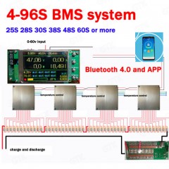
Product Name: Customize 4s -96s BMS System 34s 38s 58s 26s 35s 42s 51s 100A 150A 140A 96V 108V 120V 132V 144V 168V 180V Li Ion LiFePO4 Lto BMS Model NO.: 4S -96S Trademark: OEM Transport Package: Carton Specification: 4S Origin: China HS Code: 8541402000 Product Description customize 4S -96S BMS system 34S 38S 58S 26S 35S 42S 51S 100A 150A 140A 96V 108V 120V 132V 144V 168V 180V li ion lifepo4 LTO BMS1, real-time monitoring 4-96 series single-cell voltage, can be connected indefinitely, the current host only supports 8 modules, modular, each module manages up to 12 series , the smallest 4 series (because the module running power is taken from the battery Therefore, the total voltage of the battery connected in series with a single module cannot be less than 11v. If the battery is less than 12 strings, the excess detection channel must be connected to the positive pole of the highest battery of the module. The total voltage of the single module after input and connection must not be higher than 75v, single channel detection range is 0--5v, the input voltage of the host control part must not exceed 60v.2. Real-time monitoring of battery pack total voltage, charge and discharge current, power, temperature and statistics of actual charge and discharge capacity ah number, the host has a temperature detection and monitoring mos tube temperature, each module is accompanied by a temperature test, a total of 9 temperature detection.3, with overshoot, over discharge, over current, over temperature protection.4. Display the percentage of remaining capacity in real time and display it with the progress bar.5, high voltage 200V rated long-time working current 30A, instant short time 60A, low-voltage rated continuous working current 70A, instant short time 100A, too high voltage and current can use relay scheme, specifically can be discussed in detail, long time constant high current Work needs to strengthen the heat dissipation of the mos tube.6, running flashing instructions, prompt system operating status, 3.5-inch IPS color display, super wide viewing angle, working status at a glance.7, with current manual calibration function, because the voltage measurement error is 1.2mv total measurement error, so no calibration is needed.8, the same design of the same discharge, reduce the connection line.9. The module cascade connection mode can be used to expand the number of connection strings. In theory, it can be expanded infinitely. The two-core cat5 twisted pair cable is used to connect the host to the module, and the module and the module communicate with each other. The cable length can reach 40 meters. The effective length of the actual environmental test, if the interference is large or the wire selection is not suitable, the communication distance should be shortened accordingly).10. After the host is turned off, the module automatically goes to sleep, the power consumption is only 4ua, and the modularity can also shorten the length of the balance line, so that the host and the module, the module and the module can be placed over a long distance.11, the module has an automatic balance function, has been balanced until the voltage drop is stopped at 0.001v, the equalization current is 200ma, the function must be turned on after the battery is fully charged, the equalization discharge will generate a lot of heat, need to pay attention to the module's heat dissipation.12, fully isolated design, all interfaces can be hot swap, temperature sensor can not be used.This price is the reference price and is actually based on the number of modules.13. If you feel that the alarm buzzer sound is small, you can tear off the sticker on the surface and the sound will be loud.The two boards of the motherboard are superimposed with a size of 135x57mm and a stack thickness of 45mm without the size of the heat sink.Module size 82x72mm, stack thickness 13.8mm14, using Bluetooth 4.0 and mobile APP connection, all parameters at a glance, you can modify the host parameters through the phone, because of the use of Bluetooth 4.0, can only support Android 4.3 or above operating system, for older phones does not supportNote:Battery assembly has certain dangers, especially multiple series of high voltage. Pay attention to safety. You must have professional knowledge in this area to get started. I am not responsible for the burning and loss caused by wrong connection.The negative pole of the battery as a reference point, but also as the first cell, from the connecting Diagram is divided into B1 (the first cell ), B2 (second cell). . . Bn (n th cell).Connecting method:1. First, connect the "negative" of the battery pack to "B-" on the BMS board with the black line.2. Connect the first cable (B-) to the negative pole of the first cell, connect the second cable (B1) to the positive pole of the first cell , and the third (B2) to the second cell positive, and so on. . . Bn (the last wire) also be connected to the positive pole of the last cell, which is the positive pole (B +) of the battery.3. Use the Voltage device to detect whether the voltage of each adjacent two terminals of the cable terminal corresponds to the voltage of the battery.4. If the above steps are correct, insert the cable, and check whether the Output is equal to the total voltage of the battery pack.The meaning of the Output is:1. ) The voltage between the charger negative and B +2. ) The voltage between the load negative terminal and B +;Note:1. When installing the protection board, please fixed it firmly, be careful not to shake and other reasons caused by loose off!2. Firstly to be welded each cable to the appropriate cell pole, then put the cable terminal into the board plugs, (Please do not insert the cable terminal and then welding cells, to prevent welding damage to the protection board! )