详细说明
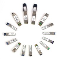
Product Name: 8.5gbps SFP+ Fiber Channel Optical Transceiver/SFP+/SFP CWDM Module Model NO.: 8.5Gbps SFP+ Fiber Channel Optical Transceiver Condition: New Certification: CE, ISO, RoHS, GS, ISO14001 Information content: Data Support Network: Ethernet Type: Wired Usage: Telephone, Computer, Workstation, Server Item Name: 8.5gbps SFP+ Fiber Channel Optical Transceiver Transmission Distance: up to 2km/10km/20km Warranty: 2~5years Delivery Time: 1~5 Days Sample Order: Available Market: Global Business Type: Manufacturer&Trading Connector: Duplex LC Trademark: Takfly Transport Package: Standard Carton Packing or Customer Required Specification: metal/PC Origin: Shenzhen, China HS Code: 8542900000 Product Description 8.5Gbps SFP+ Fiber Channel Optical TransceiverFeatures:Up to 8.5Gb/s bi-directional data linksHot Pluggable SFP+ footprintnm DFB transmitter, PIN photo-detectorTransmission distance up to 2km/10km/20km on 9/125 μm SMFDigital Status monitoring InterfaceDuplex LC connectorRoHS compliant and Lead Free metal enclosure for lower EMI Single 3.3V power supplyOperating case temperature: 0to 70Compliant with FC-PI-4 800-Mx-SN-I, SFF-8431 ,SFF-8432 and SFF-8472Applications:Tri Rate 1.0625/2.125/4.25/8.5Gbs Fiber Channel Product description:DF-318G-LRC transceivers are designed for using in Fiber Channel links up to 8.5Gb/s data rate over multimode fiber and compliant to SFI electrical specifications. The transmitter input and receiver output impedance is 100 Ohms differential.Data lines are internally AC coupled.The module provides differential termination and reduce differential to common mode conversion for quality signal termination and low EMI.Pin definition:The SFP+ modules are hot-pluggable. Hot pluggable refers to plugging in or unplugging amodule while the host board is powered. The SFP+ host connector is a0.8 mm pitch 20 position right angle improved connector specified by SFF-8083, or stacked connector with equivalent with equivalent electrical performance. Host PCB contact assignment is shown in Figure 2and contact definitions are given in Table 2. SFP+ module contacts mates with the host in the order of ground, power, followed by signal as illustrated by Figure 3and the contact sequence order listed in Table 2.Table 2: SFP+ Module PIN DefinitionAbsolute maximum ratingThese values represent the damage threshold of the module. Stress in excess of any of the individual Absolute Maximum Ratings can cause immediate catastrophic damage to the module even if all other parameters are within Recommended Operating Conditions.ParametersSymbolMin.Max.UnitPower Supply VoltageVCC0+3.6VStorage TemperatureTc-40+85°COperating Case TemperatureTc0+70°CRelative HumidityRH595%Table 3: Absolute Maximum RatingRecommended operating environmentRecommended Operating Environment specifies parameters for which the electrical and optical characteristics hold unless otherwise noted.ParameterSymbolMin.TypicalMaxUnitPower Supply VoltageVCC3.1353.3003.465VOperating Case TemperatureTC02570°CTable 4: Recommended Operating EnvironmentLOW Speed CharacteristicsParameterSymbolMin.TypicalMaxUnitPower Consumption1.21.2WTX_Fault,RX_LOSVOL00.4VVOHHost_Vcc-0.5Host_Vcc+0.3VTX_DISVIL-0.30.8VVIH2.0VCCT+0.3VRS0,RS1VIL-0.30.8VVIH2.0VCCT+0.3Electrical characteristicsTransmitter Input Characteristics ParameterConditionsSymbolMin.TypicalMaxUnitNominal Data RateVID2.1258.58.5GbdReference Differential Input ImpedanceZd100ΩInput AC Common Mode Input Voltage025mV(RMS)Differential Input Voltage SwingVID150900mVDifferential Input S-parameter0.01-3.9GHzSDD11-10dB3.9-8.5GHzNote1Note1Differential to Common Mode Conversion Note 20.01-8.5GHzSCD11-10dBData Dependant JitterDDJ0.1UI(p-p)Total JitterTJ0.28UI(P-P)Uncorrelated JitterUJ0.023RMS1) Differential Return Loss given by equation SDD11(dB) =-8+13.33 Log10(f/5.5), with fin GHz2) Common mode reference impedance is 25. Differential to common mode conversion relates to generation of EMIReceiver Output Characteristics ParameterConditionsSymbolMin.TypicalMaxUnitNominal Data RateVID2.1258.58.5GbdReference Differential Input ImpedanceZd100ΩTermination MismatchΔZd5%Output AC Common Mode Input Voltage15mV(RMS)Output Rise and Fall time20% to 80%tRH, tFH35psDifferential Input Voltage SwingZload=100ohmVOD350800mVDifferential Input S-parameter0.01-3.9GHzSDD22-10dB3.9-8.5GHzNote1Note1Differential to Common Mode Conversion Note20.01-6.5GHzSCCD22-7dBDifferential to Common Mode Conversion Note26.5-8.5GHzSCCD22-3dBData Dependant JitterDDJ0.42UI(p-p)Total JitterTJ0.71UI(P-P)1) Return Loss given by equation Sxx22(dB) =-8+13.33 Log10(f/5.5), with fin GHz2) Common mode reference impedance is 25. Common mode return loss helps absorb reflection and noise improving EMIGeneral SpecificationsParameterSymbolMin.TypicalMaxUnitNotesData RateDR1.06252.1254.258.5Gb/secFiber Length on 9/125um SMFL20km120km220km320km41) At 1.0625 Gb/s Fibre Channel data rate.2) At 2.125 Gb/s Fibre Channel data rate. 3) At 4.25 Gb/s Fibre Channel data rate.4) At 8.5 Gb/s Fibre Channel data rate.Optical characteristicsParameterSymbolMin.TypicalMaxUnitNotesTransmitterCenter Wavelengthλt128413101345nmRMS spectral widthPm--1nmAverage Optical PowerPavg-9.0--1dBm2Extinction RatioER3.5--dB3,4,5,6Relative Intensity NoiseRin-128dB/HzReceiverCenter Wavelengthλr1260-1360nmReceiver SensitivityPsens---14.4dBm3Psens-18dBm4Psens-23dBm5Psens-25dBm6LOS AssertLos-30-dBmLOS De-assert-19OverloadPin---1.0dBm3Receiver Reflectance---12dBNote: 1. The following optical characteristics are defined over the Recommended Operating Environment unless otherwise specified. 2.The optical power is launched into MMF 3.Measured with aPRBS 27-1 test pattern @8.5Gbps,BER≤10-12 2km/10km/20km 4.Measured with aPRBS 27-1 test pattern @4.25Gbps,BER≤10-12 2km/10km/20km. 5.Measured with aPRES 27-1 test pattern @2.125Gbps,BER≤10-12 2km/10km/20km. 6. Measured with aPRES 27-1 test pattern @1.0625Gbps,BER≤10-12 2km/10km/20km.Digital Diagnostic FunctionsThe following digital diagnostic characteristics are defined over the Recommended Operating Environment unless otherwise specified. It is compliant to SFF8472 Rev9.2 with internal calibration mode. For external calibration mode please contact our sales stuff.ParameterSymbolMin.MaxUnitNotesAccuracyTransceiver TemperatureDMI_Temp-3+3degCOver operating tempTX Output optical powerDMI_TX-3+3dBRX Input optical powerDMI_RX-3+3dB-3dBm to -12dBm rangeTransceiver Supply voltageDMI_VCC-0.08+0.08VFull operating rangeBias current monitorDMI_Ibias-10%10%mADynamic Range AccuracyTransceiver TemperatureDMI_Temp-570degCTX Output optical powerDMI_TX-9-1dBmRX Input optical powerDMI_RX-180dBmTransceiver Supply voltageDMI_VCC3.03.6VBias current monitorDMI_Ibias016mAOur products cover:Patch Cords,Pigtail /MPO(MTP)/ Optical Fiber Cable/Optic Terminal Box /ODF,Patch Panels /Optic Splice Closure /SFP Module/ Media Converter /Video Optical transceiver /Connector /Adapter /AttenuatorCoupler /PLC Splitter /CWDM /DWDM /FWDM /OADM etc.Any questions or requirements just feel free to contact me